|
|
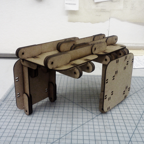
The magic wallet contains a "switching hinge." It can hinge from either edge. I became really interested in this type of joint/trick and decided that it could be interesting to try and make it big. Out of OSB. |
|
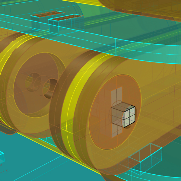
I decided that the most important thing to study would be a hinge assembly using OSB. I also used this small sub-exercise as a way to become more familiar with the Shopbot. |
|
This was my first CNC workflow hiccup. The first of many. The dreaded inside-the-line-outside-the-line-switcheroo. So, because the hinge test at full scale failed, I decided to make some scaled down tests using lasercut masonite. |
|
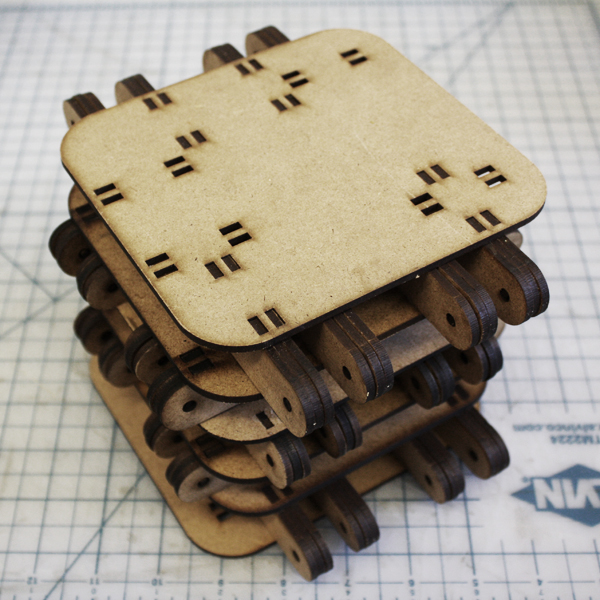
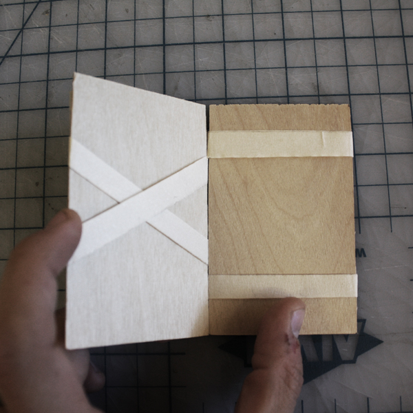
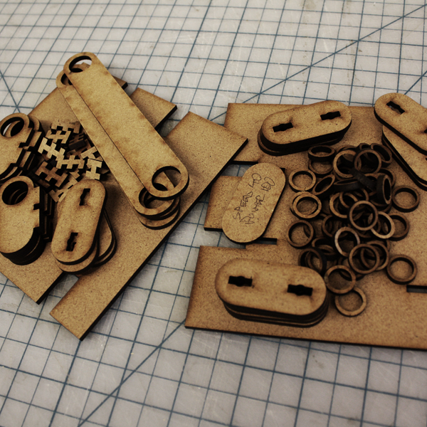
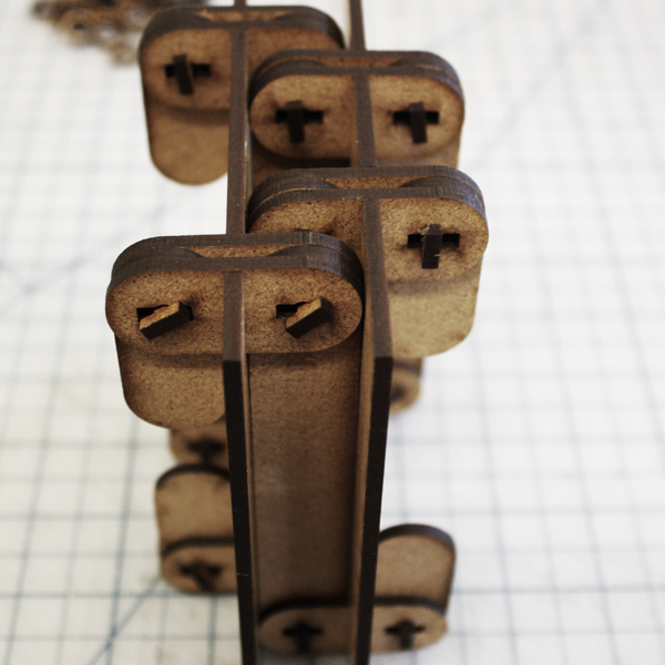
The first masonite prototype was cut on the epilog (power 100, speed 40, frequency 500). My goal with this assembly was to successfully create the magic wallet switching hinge condition. |
|
I used the same basic hinge design from the full scale mockup to see if it would really work. However, I made the mistake of thinking that I would need the hinge
mechanism to wrap around to the back of each of the two "boards." |
|
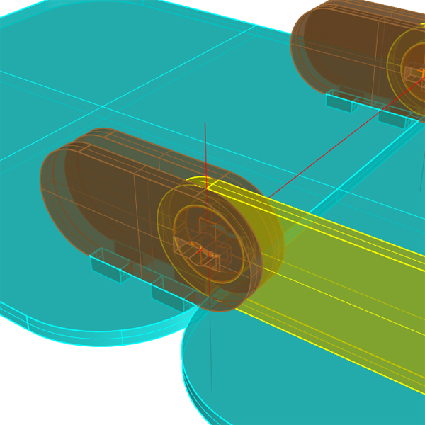
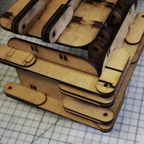
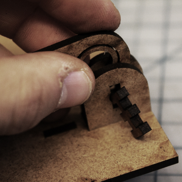
Here you can see the portion of the hinge that wraps around to the rear of the back, which creates the need for there to be double joints at each hinge. |
|
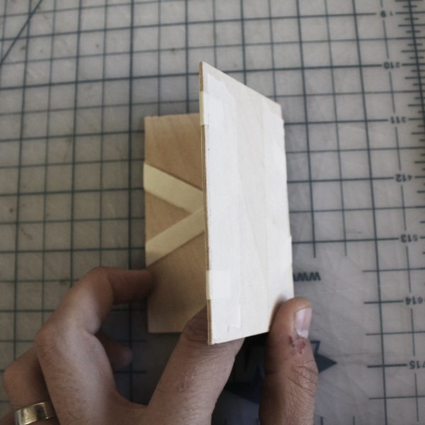
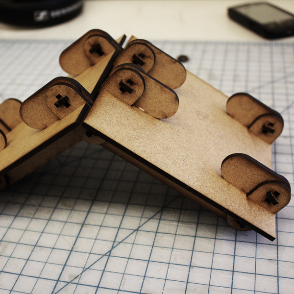
The double joint was mostly due to another initial mistake in thinking that the rotational center point needed to be in from the edge of the board. Here you can see the failure of the piece to open past 90 degrees. |
|
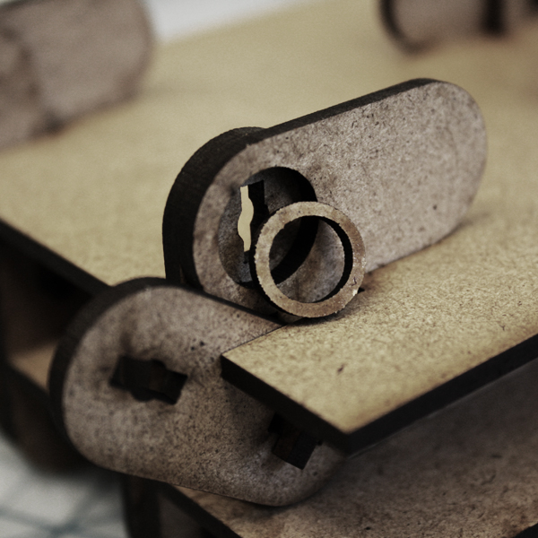
So the first mockup was a double jointed failure, but it was a successful failure in that it did actually correctly simulate the magic wallet hinge-switch. The hinge joint needed some work though. |
|
I used a 1/8" end mill for all the tool paths and had some initial troubles with getting the machine to cut all the way through the material, so I ended up taking 5 passes to cut each piece or hole out. |
|
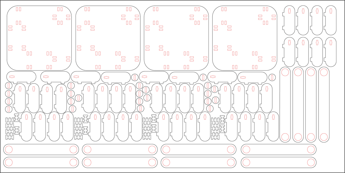
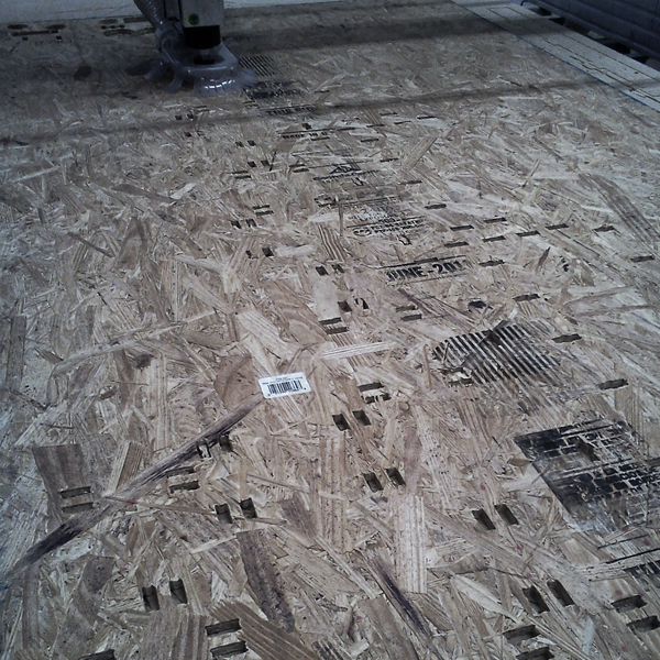
In hindsight it is easy to see that the detail in the cut outs was too detailed and also too differentiated across the whole assembly. Here is the endless sea of cut outs. |
|
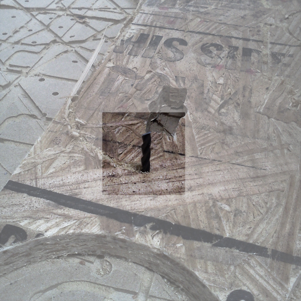
To a cnc expert, this picture is probably scary. You can see how much of the material is disappearing due to the heavy nesting of pieces. You can see that completely usupported (not screwed down) corner of material. Soon after this, disaster struck. |
|
Because that chunk of material was not screwed down, the osb climbed the bit which snapped almost immediately. I want my vacuum table. |
|
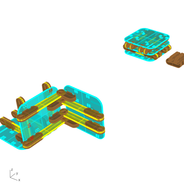
Following the pattern from the first prototype, after this epic fail, I decided to make the assembly out of masonite again. And I took this opportunity to adjust the hinge assembly to make the cnc process a little easier next time around. My
goals were to reduce the number of inside corners both for machining purposes (curves and circles appear to be easier for the machine to do) and for digital process
purposes as it was cumbersome to set up a file with hundreds of inside corners. |
|
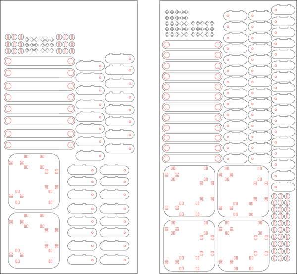
For the final milling, I spoke with Andrew Manto from RPL and got a few pointers. I had a few fundamental problems.
First off, I actually had more pieces to cut this time, so time would be an issue. However, the inside profile cuts were much simpler. So simple in fact
that I decided to use a 1/4" end mill for everything. This meant I could cut in just two passes. The other problem was the close nesting. I had only the two sheets to use,
so I couldn't space things out any more. Andrew suggested the GAME CHANGER: A drill pass. |
|
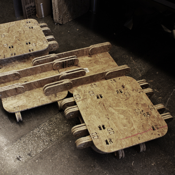
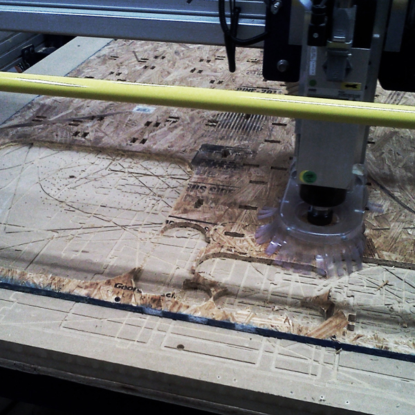
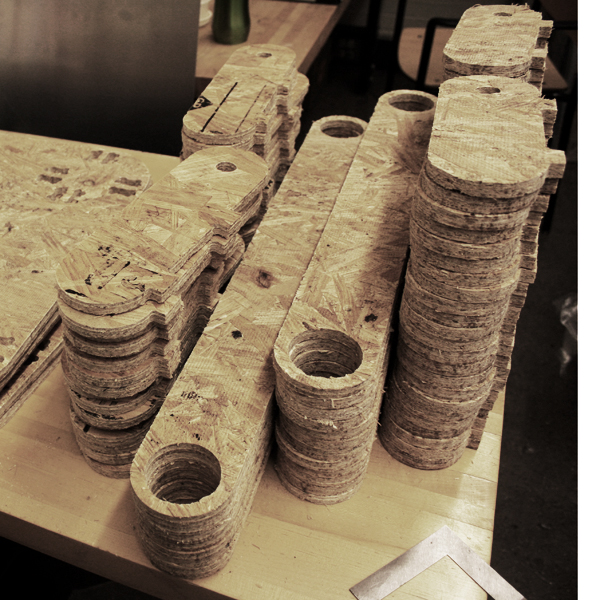
So, in order to prevent the pieces and sheet from pulling up, I had the mill go through and place a "drill mark" in two places for every piece. I then followed with a screw gun and fastened each piece down. This
added time to the job, but since I was able to cut faster it worked out in the end, and I cut through the two sheets in just about 4 hours. NO BROKEN BITS. |
|
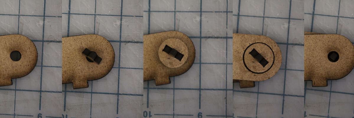
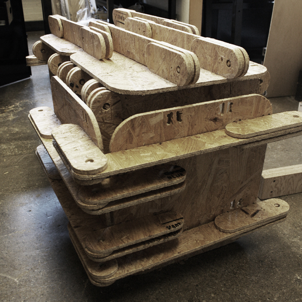
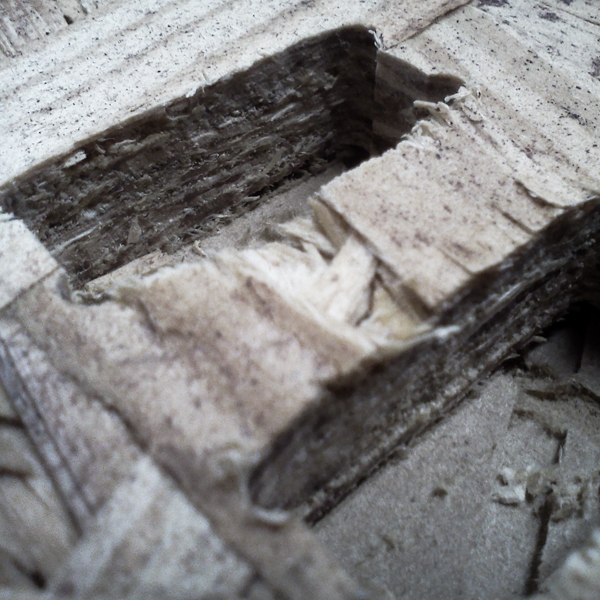
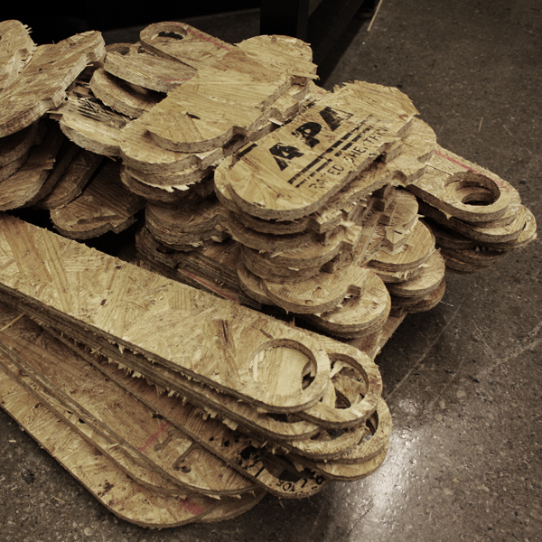
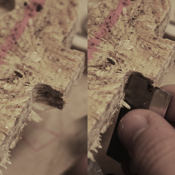
There was an onion skin left on most pieces and a frayed edge once the pieces were pulled out of the sheet they were cut from. I used a metal edge (first a razor blade until I cut myself, and then a small steel ruler for the rest) to remove the gunk. |
|
nice. |
|
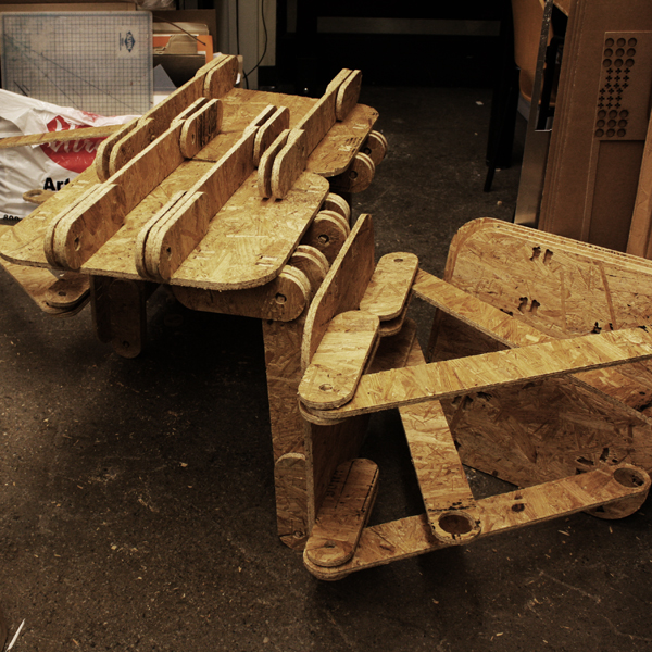
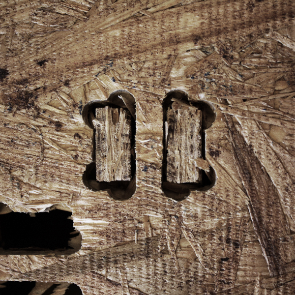
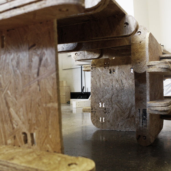
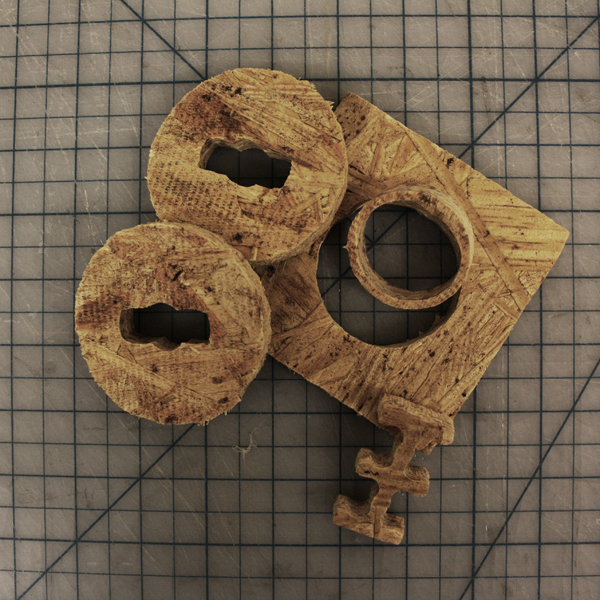
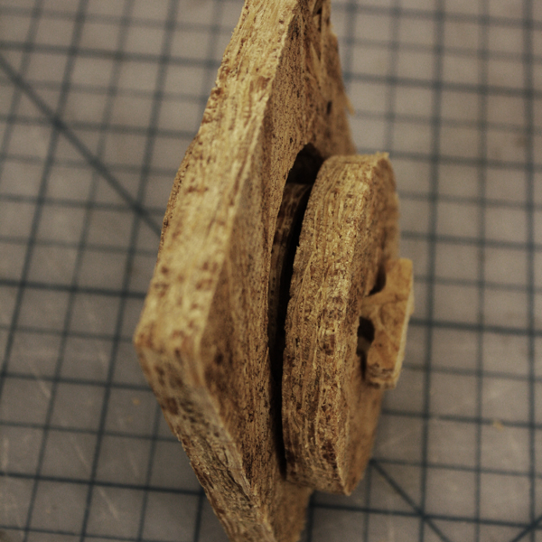
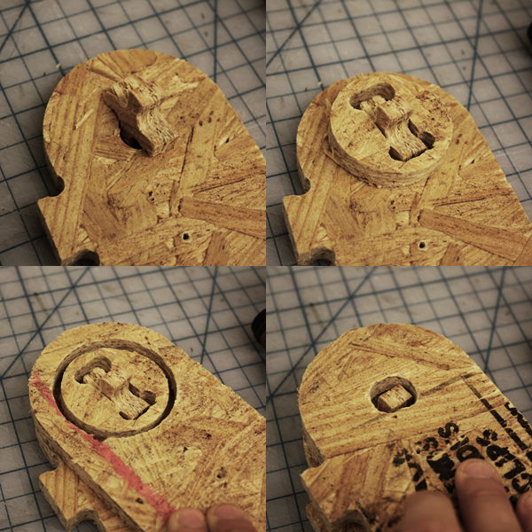
The final hinge detail at full scale. OSB is not the right material for this project. |
|
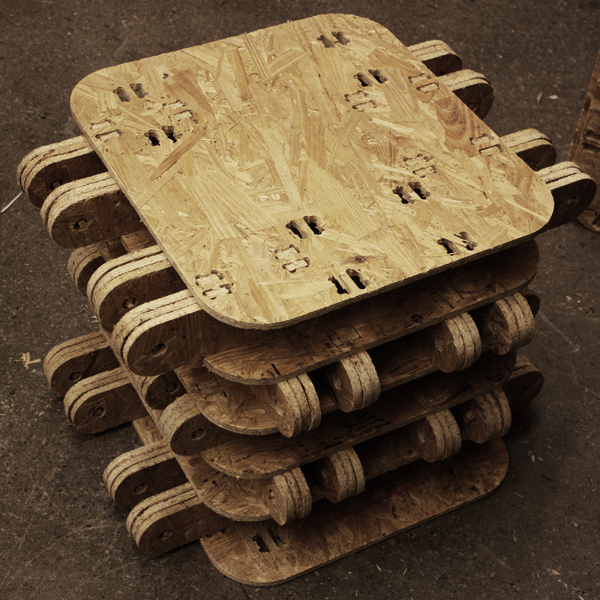
Look at me. I don't know what I am. |